Friday, May 3, 2013

The Importance of Ozone

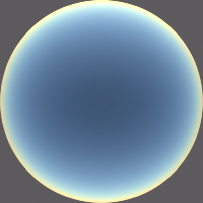
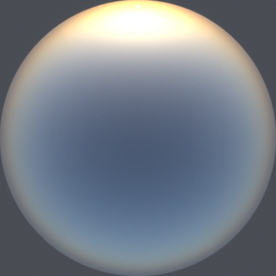
As I've written about before (in particular here and here), ozone absorption has a big influence on the color of the sky during twilight. In particular, ozone absorption gives the sky its increasingly saturated blue color as the sun sinks below the horizon. You can easily see this effect in real life, especially if you are looking out the window from inside and your eyes are adjusted to the unchanging hue of indoor light. I recently rendered a new pair of images (below) to clearly illustrate the effects of ozone. I hadn't rendered before-and-after ozone pictures since adding aerosols to the atmosphere, so I wanted to create these updated images. The solar elevation angle in these renders is −4°. These are display-linear images—I haven't done anything to increase the saturation or contrast.

Twilight with ozone.

Twilight without ozone.

Thursday, April 25, 2013

Poster and Presentation

Here's a simple poster that summarizes my sky renderer project:


And here's a quick presentation that summarizes the project (I spoke over this when presenting it, so much of it doesn't have words; some of it won't make sense without narration):


Friday, February 1, 2013

New CMFs and More Accurate Spectrum Renders

I updated the color matching functions (CMFs) that my spectral rendering system uses to convert spectral power distributions to CIE XYZ. My new CMFs are the new, physiologically-relevant, 2-deg XYZ CMFs transformed from the CIE (2006) 2-deg LMS cone fundamentals. My old ones were the CIE 1931 2-deg, XYZ CMFs modified by Judd (1951) and Vos (1978).

I made some new images of the visible spectrum rendered into the sRGB color space. When you convert XYZ to sRGB you get negative color components when the color lies outside the sRGB gamut. Clipping these negative components to zero distorts the color. But if you add white light to the entire spectrum, you can bring the negative components into the displayable range, resulting in an accurate picture of what the spectrum looks like on a gray background. In each gray background image below, I added just enough white light to bring the most negative value to zero, and I set the range so that the most positive value maps to one. In each of the darker, black background images, I simply removed the white light. And in each of the brighter, black background images, I brightened the spectra just enough to utilize the entire displayable range.

New spectrum on gray.
Wavelength range: 390–830 nm.

New spectrum on black.
Wavelength range: 390–830 nm.

New spectrum on black, brightened.
Wavelength range: 390–830 nm.


New (top) and old (bottom) spectra on gray.
Wavelength range: 380–830 nm.

New (top) and old (bottom) spectra on black.
Wavelength range: 380–830 nm.

New (top) and old (bottom) spectra on black, brightened.
Wavelength range: 380–830 nm.


Old spectrum on gray.
Wavelength range: 380–825 nm.

Old spectrum on black.
Wavelength range: 380–825 nm.

Old spectrum on black, brightened.
Wavelength range: 380–825 nm.

Sunday, January 13, 2013

Sunny Bunny

Below is a new bunny render, lit by a new sky render with a solar elevation angle of 45°. Apart from the sky map and the exposure, the setup is identical to the bunny images in the previous post.

Bunny lit by 45° sun.

Here's a low dynamic range version of the sky render that I used to light the image above:

45° solar elevation angle.

Here's another new sky with a lower sun, shown here with the same exposure as the image above:

30° solar elevation angle.

I rendered these sky renders directly to equirectangular format. I rendered them at high resolution to more accurately capture the shape of the sun. The sun isn't visible in the images above because the sky around the sun is blown out. The images above are both re-exposed so that you can see the blueness of the sky, but I originally rendered them 3 stops lower to ensure that the bright sun could not exceed the half-precision floating-point maximum value (because the renders are saved as 16-bit OpenEXR images).

Here are LDR versions of the images with unmodified exposure:

45° solar elevation angle.

30° solar elevation angle.

By the way, the ground color in the bunny render doesn't match that in the sky render—the bunny render ground is tan, and the sky render ground is gray.

I also rendered some images of a gold bunny lit by the same 45° sun and sky, featuring photon-mapped caustics: http://photorealizer.blogspot.com/2013/01/gold-bunny-lit-by-sun-and-sky.html

Monday, December 31, 2012

Rendering Using Sky Images as Light Sources

I rendered the following bunny images in Photorealizer using equirectangular HDR sky images as light sources.

Bunny at sunrise / sunset.

Bunny during twilight.

Below are LDR versions of the sky images that I used for the bunny renders above. These are the same images that I posted and described in the previous post.

Sunrise / sunset.

Twilight.

Note the realistic deep blue tone of the twilight images. This blue is a result of ozone absorption. Without ozone, these images would be a dull gray.

Sunday, December 30, 2012

Converting Between Fisheye and Equirectangular

I used Photorealizer to convert some of my recent fisheye sky renders to equirectangular (latitude–longitude) format. To give Photorealizer the capability to do this, I copied the panoramic cameras from the sky renderer to Photorealizer, and gave Photorealizer the ability to use a high dynamic range fisheye image as an environment map. Then, to do the actual conversion, I simply set up an environment map using a sky renderer render, and rendered a picture of it using the equirectangular camera (an analogous process could be used to convert from equirectangular to fisheye).

I wanted to convert the fisheye images to equirectangular format because Photorealizer already supports importance sampling for equirectangular environment maps. I plan to use these images as light sources for Photorealizer renders, so being able to sample them efficiently—even when they contain the sun—is very important.

Alternatively, I could have used existing software to do the conversion, but I prefer to do things myself when possible. Or I could have re-rendered the sky images in equirectangular format, but that would have taken a long time. The way I did the conversion worked very well, and it let me add features to and make improvements to Photorealizer in the process.

Here are two sets of before and after images:

Before: sunrise / sunset fisheye render.

After: converted to equirectangular format using Photorealizer.

Before: twilight fisheye render.

After: converted to equirectangular format using Photorealizer.

I recently made some other relevant improvements to Photorealizer as well, which you can read about on my Photorealizer blog:
http://photorealizer.blogspot.com/2012/12/environment-map-improvements.html
http://photorealizer.blogspot.com/2012/12/photon-mapping-with-hdr-environment-maps.html

Monday, December 3, 2012

Twilight with Aerosols

Here are two new twilight images that I rendered with aerosols. I haven't tone-mapped either of these images—they are display-linear. In the second image, the sun is lower, there is a lower concentration of aerosols in the atmosphere, and the ground has a desert-like reflectivity. Because the aerosol concentrations and ground reflectivities differ, the images are not directly comparable, but I believe that a few of the differences are due to factors besides the aerosols. Based on my research (including Color and Light in Nature and The Influence of Ozone and Aerosols on the Brightness and Color of the Twilight Sky) and observations, at −4.8° I would expect a more defined twilight arch, an area of low saturation purple above the twilight arch, and more saturated blue in the zenith direction. All of these phenomena seem to be present in the −4.8° render.

−3° solar elevation angle.

−4.8° solar elevation angle. Half the amount of aerosols as in the
image above.

Wednesday, November 28, 2012

Comparison

Here's a current render from my sky simulator compared with one from Hosek and Wilkie's (one of the path tracer renders from their paper, scaled up to the same size as my render). I purposely matched the lens, the solar elevation angle, and the exposure, however I did not try to match the atmospheric properties, ground albedo, or tone-mapping. There are a few images in the Hosek–Wilkie paper with a solar elevation angle of 4°, and I simply chose the one that matched my render from the previous post most closely (which was the one with a turbidity of 6), then I re-exposed my (HDR) render to match the Hosek–Wilkie one as well as possible. Besides the numerous differences in the simulations themselves, there a few notable differences between these two images: Hosek and Wilkie's is tone-mapped while mine is not, mine uses a fisheye lens that extends beyond 180° to show the ground, and mine includes the solar disc. In spite of the differences, the images look remarkably similar to me. Using the lightbox, you can toggle between the two images.

My sky simulator.

Hosek and Wilkie's sky simulator.

Tuesday, November 27, 2012

Aerosols

With aerosols. Solar elevation angle 4°.

No aerosols. Solar elevation angle 4°. Same exposure as the image above.

I made a first pass at adding aerosols to the atmosphere. Aerosols have a significant impact on the appearance of the sky, but simulating them isn't particularly straightforward: the types and levels of aerosols vary widely by region (e.g., city vs. forest vs. ocean) and other factors, and computing their scattering properties is quite complicated.

I used the representative profile of aerosols in Elterman's paper UV, Visible, and IR Attenuation for Altitudes to 50 km, 1968. The paper provides aerosol extinction coefficients that vary based on altitude and wavelength. It's the same data used in The Influence of Ozone and Aerosols on the Brightness and Color of the Twilight Sky, which is what led me to the paper in the first place. I used the provided scale height relationship (scale height of 1.2 km) to extrapolate the data beyond 50 km.

For the scattering phase function, for now I just used the Henyey-Greenstein phase function, which I had already implemented for Photorealizer, including analytic scattering direction sampling. For now I used a constant asymmetric parameter of 0.7 (which means that the mean cosine of the scattering angle is 0.7, which implies strong forward scattering), which seems to be a pretty good average value based on my research. I plan to implement Cornette and Shanks's modified version of the Henyey-Greenstein phase function, which better approximates actual Mie scattering phase functions and converges to the Rayleigh phase function as the asymmetry parameter approaches zero.

I used a constant single scattering albedo of 0.9, which, like my asymmetry parameter, seems to be a pretty good average value based on my research. At the sampled extinction distance, I scatter the photon/ray with 90% probability, and absorb it with 10% probability.

I changed the Earth's surface to have an albedo of 31%, which seems to be the accepted average albedo of Earth's surface. At some point, I would like to make a procedural ground, or use a map of the actual Earth. Procedural mountains would be particularly nice for showing off atmospheric effects.

My aerosols system could be improved in many ways. In particular, I could use a realistic particle size distribution, use realistic particle type proportions (each type having a certain index of refraction, with real and imaginary parts), and then compute scattering and absorption properties using the Mie solution to Maxwell's equations. That sounds like it might be overkill for now, although I'm sure I would learn a lot in the process. 

Wednesday, November 21, 2012

Unbiased Distance Sampling

I implemented an algorithm for unbiased distance sampling in heterogeneous media, which replaces the biased ray marching in my sky renderer. It's a Monte Carlo algorithm, "Algorithm 1" in the paper Unbiased Global Illumination with Participating Media. I learned about that paper from Hosek and Wilkie's sky model paper. The algorithm originates from a 1968 paper by Coleman, which I'm interested in looking at, but which I haven't been able to locate.

The algorithm samples a random distance based on the highest extinction (or scattering or absorption) coefficient along the ray (or line segment in my case), or any coefficient greater than or equal to that (such as the highest in the entire medium, which is often easier to find). Then it probabilistically takes another leap based on the actual coefficient at the sampled location.

Algorithm from Unbiased Global Illumination with Participating Media.

Using the lowest max coefficient allows larger steps to be taken, which decreases the number of steps needed and increases performance. Since Rayleigh and ozone scattering and absorption coefficients vary predictably based on wavelength, the lowest max coefficient can be found for given wavelength, and with Rayleigh scattering, the lowest coefficient along the line segment can be found by using the coefficient at the point on the line segment that is closest to the center of the Earth (assuming density is monotonically decreasing with altitude).

After implementing this algorithm and the related optimizations, not only are my renders unbiased, but they are also 5 to 10 times faster—a pretty huge speed increase.